Same TrustClarity. New revamped look!
Learn more about our new lookLoading...
We use cookies to enhance your experience, personalize content, and analyze traffic.
Cookie PolicySame TrustClarity. New revamped look!
Learn more about our new lookSlide 1 of 1
Manufacturer
Kaelus
MPN
TMA2117F00V1-1
Available
1
Condition
New
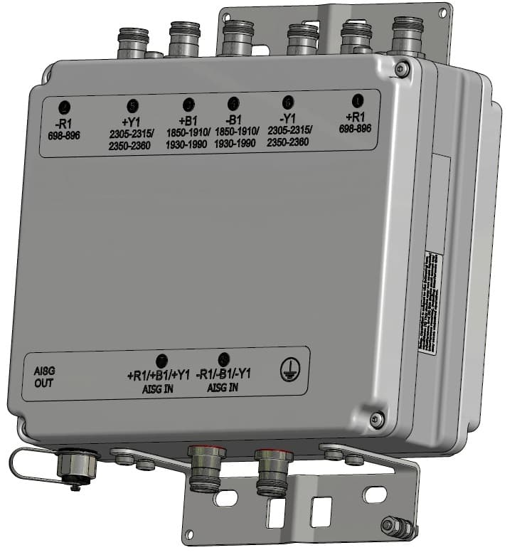
Kaelus TMA2117F00V1-1 - Pcs / Wcs Dual Band Twin Tma, With 700/850 Bypass, Aisg2.0
The Kaelus TMA2117F00V1-1 is a high-quality, dual band twin TMA (Tower Mounted Amplifier) designed for use in wireless communication systems. This TMA is equipped with 700/850 bypass capability, allowing for seamless integration with existing networks. It also features AISG2.0 compatibility, providing advanced remote control and monitoring capabilities.
This TMA is designed to improve signal strength and quality in both the 700 MHz and 850 MHz bands, making it ideal for use in LTE, CDMA, and GSM networks. It is capable of handling high power levels, making it suitable for use in high traffic areas. The Kaelus TMA2117F00V1-1 is a compact and lightweight unit, making it easy to install on towers or rooftops.
Improved base station sensitivity through gain in 1900 and WCS bands
High Linearity and low noise performance; Bypass provided for 700/850MHz services
Hardware and software configuration using AISG “Personality” upload
Fail safe bypass mode with lightning protection
Technical Specifications | ||
Band Name | 1900 | WCS |
Downlink | ||
| Passband | 1930 - 1990MHz | 2350 - 2360MHz |
| Insertion loss | 0.5dB typical | |
| Return loss | 18dB minimum | |
| Maximum input power | 160W (average) / 2kW (PEP) | 120W (average) / 1.2kW (PEP) |
Uplink | ||
| Passband | 1850 - 1910MHz | 2305 - 2315MHz |
| Gain | 13dB | 12dB |
| Variable gain | 3dB to 13dB in 1dB steps (controlled by AISG commands) | 2dB to 12dB in 1dB steps (controlled by AISG commands) |
| Gain variation | ±1dB maximum | |
| Return loss | 18dB minimum operating, 12dB in bypass | |
| Bypass loss | 2.5dB typical | 3.3dB typical |
| Noise figure | 1.4dB typical | 1.7dB typical |
| Output IP3 | +30dBm typical | |
| Maximum input power with no damage | +12dBm maximum | |
| Rejection | 27.5dB minimum@2324.54 - 2341.285MHz | |
Low Band Path | ||
| Passband | 698 - 896MHz | |
| Return loss | 18dB minimum | |
| Insertion loss | 0.35dB typical | |
| Maximum input power with no damage | 200W (average) / 2kW (PEP) | |
Electrical | ||
| Impedance | 50Ohms | |
| Intermodulation products | -153dBc maximum in RX band with 2 x 20W carriers | |
Power Supply And Alarm (Current Window Alarm Mode, Default) | ||
| DC supply voltage | 8.5 to 30V DC, case is DC ground | |
| DC supply | Each BTS powered individually (programmable) | |
| DC supply current, normal mode | 200 ± 20mA per port (programmable) | |
| DC supply current, alarm mode | 300 ± 30mA per port(programmable) | |
Aisg Mode Of Operation (Auto Selected On Valid Aisg 2.0 Frames) | ||
| DC supply voltage | +8.5V to +30V DC | |
| AISG version | 2.0 (1.1 optional) | |
| Supply current, AISG mode | 400mA @ 8.5V, 120mA @ 30V typical | |
| AISG connector, current rating | IEC60130-9, 8-pin female ,< 4A peak, 2A continuous, pin 6 | |
| Field firmware upgradable | Yes | |
Environmental | ||
| Temperature range | -40ºC to +65ºC | -40°F to +149°F | |
| Ingress protection | IP67 | |
| Lightning protection | IEC61312-1, RF: ±5kA maximum (8/20us), AISG: ±2kA maximum (8/20us) | |
| MTBF | >1,000,000 hours | |
Mechanical | ||
| Dimensions H x D x W | 300 x 250 x 118mm | 11.81 x 9.84 x 4.65in | |
| Weight | 11.8kg | 26lbs | |
| Finish | Painted, light grey (RAL7035) | |
| Connectors | DIN 4.3-10 (F) x 8 long shank, AISG (F) x 1 | |
| Mounting | Pole/wall bracket supplied with two metal clamps 45-178mm diameter poles | |
Please refer to the following attachments for additional details on the product.
No specifications available.